I Case Study
First, I choose the Kartal Master Plan, designed by Zaha Hadid's studio, as a parametric Urbanism Case Study. The Kartal Master Plan is a proposal for a new district development of Istanbul, Turkey.
Master Plan
(http://www.zaha-hadid.com/masterplans/kartal-pendik-masterplan/)
Perspective
(http://www.zaha-hadid.com/masterplans/kartal-pendik-masterplan/)
II Parametric Modeling in Urban Design
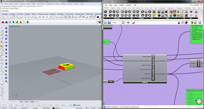
Due to the limited information of the Kartal Master Plan, I did not remodel the whole Master Plan. In this project, I focused on how to use the attractor approach to control the urban space in rhino and grasshopper.
The Urban Space control is made in two scales, the block scale and building type scale.
1 Basic Grid Block
At the begin, I created an original basic grid system in grasshopper, which means the road center line.
Screenshot 1
2 Block Form Control
1) Change Block Size by Attractor Points
Based on the original basic grid, individual control points were add in it. Each point has a attraction or a repulsion. I used the vector calculation between each intersection and control points to change the block form.
We can use the block size factor to change the block size. When the factor is positive number, it means the attractor point has the repulsion and it will enlarge the around block size. Instead, the negative number means the attraction from the control point, which will decrease the around block size.
If you move the control point, the block boundary will change.
2) Road Width Control
After creating polylines by intersection points and scale the polylines by road width rate, the block boundary was got.
If you move the control point, the block boundary will change.
3) Block Height Control by Attractor Points
For the block height control, I use the same attractor points as the block size control. By using the vector calculation in the direction of z axis, it got the different height number according to the distance between block corner to the attractor points.
Screenshot 4
By using the eight corner points of the block, the block mesh was created.
Screenshot 5
Screenshot 6
3 Building Form Control
The attractor approach can also be used to change the building types.
1) Public Frontage Space Dimension
I used the same attractor points to generate various frontage space from towers to low rise buildings. The towers have larger frontage space to the street than low rise buildings. The space dimension was remapped according to the distance between the center of each block to the attractor points.
In order to get the obvious influence from multiply attractor points, I use the square of the distance between each block center to the attractor as the basis for remap. Then it got the a series of frontage space dimension. Then it got the a series of frontage space dimension.
Screenshot 7
2) Courtyard Dimension
Using the same method of remap, the gradual change of the courtyard dimension was created.
It got the building mesh by cutting the frontage space and courtyard from the block mesh.
Screenshot 9
Screenshot 10
3) Split Block
At last, each blocks are divided into four parts for a secondary circulation system. After cutting the space for circulation, it shows the final master plan.
Screenshot 11
Screenshot 12
Rendering Perspective
III Physically-based model
I choose several high rise buildings in the master plan to do the physically-based model.
Screenshot 13
Screenshot 14
Ref:
1 http://www.grasshopper3d.com/profiles/blogs/urbanism-attractor-technique
2 http://www.zaha-hadid.com/masterplans/kartal-pendik-masterplan/
3 http://www.patrikschumacher.com/Texts/Parametricism%20-%20A%20New%20Global%20Style%20for%20Architecture%20and%20Urban%20Design.html


